We found that giving it a push and releasing it at the end gave it the larger distance. Ruby and ours ended up going the furtherest which we are proud of.


Object
|
Design guidelines
|
Material
|
|---|---|---|
| Counterweight | 75 to 100 times heavier than projectile | should be adjustable |
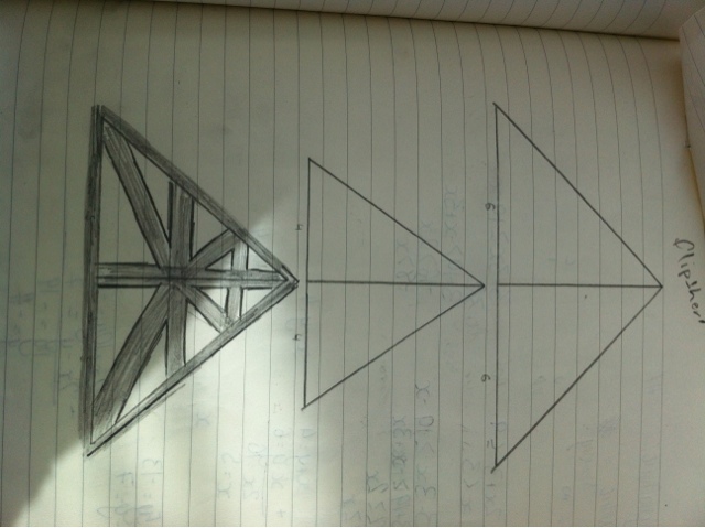
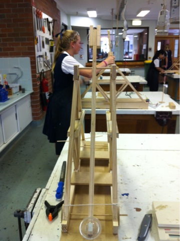
| Arm | angle should be about 45 degrees when cocked; upper part of arm should be 3 to 5 times longer than the lower end | pvc pipe |
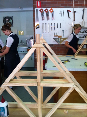
| Base and framework | must be heavy enough to support arm and counterweight and for precision, yet light enough to have a high material efficiency | pvc pipe |
| Sling or rope | should be slightly shorter than upper part of the throwing arm (for starters, that is); too short will release the projectile too early, higher trajectory; too long will drag the ground, lower trajectory | any material |
| Sling release pin | a more hooked prong will hold the sling loop longer than a straighter one. ie a prong less hooked or in line with beam gives an earlier release, higher trajectory;a prong more hooked or forward-pointing gives a later release, flatter trajectory | metal or other material |
| Projectile | a heavier projectile tends to pull the loop off the prong earlier than a lighter projectile does. heavy projectile gives earlier release, higher trajectory; light projectile gives later release, flatter trajectory | tennis ball-provided |
| Trigger | you need some way to release the projectile in a repeatable way | any material |
| Trough | the projectile needs to slide down some type of guide; friction will be important here | any material |
| *Base wheels-optional | wheels added to the base may increase distance; repeatability(? ) | any material |


|
Materials
|
Use
|
Characteristics
|
Properties
|
|
Plywood
|
The ‘chassy’ of my design. It keeps all the other materials used
to power my kart secure.
|
Very light weigh however it is not ‘flimsy’ and does not break
easily. With a power saw, it is easy to c
|
Approximently 4mm thick, 11cm long and a varing width of 4cm –
0.1cm.
|
|
Small gear
|
Attached to the motor, it interlocks with the larger motor,
thus, transferring the electrical energy within the motor into kinetic
energy; spinning the wheels.
|
It is made up of a plastic and the cog has a small hole through
the center of it. This hole is a ‘push fit’ insuring that it is attracted to
the motor.
|
It has 8 indents which interlock with the larger wheel and an
approximate 0.3cm diameter.
|
|
Large Gear
|
Attached to the back Axel, this large gear. Interlocking with
the smaller gear, this large gear turns the wheel.
|
“as above”
|
|
|
Motor with +ive and –ve
wires
|
To covert the electrical energy into kinetic energy
|
It is make of metal with a plastic cap on one end of the motor.
|
Has a metal point that the small cog is attached to. Also has
coloured positive and negative wires, pre soldered to the opposite end.
|
|
X2 Large wheels
|
To transfer the kinetic energy from the motor and use that
energy to drive the kart forward
|
A circular diameter with the grip and tire cap removed. Has an
opening on the inner side. Alowing the axel to press fit – so it does not
slide off.
|
The tire came with a cap and grip tire, but I had removed them.
|
|
x2 small wheels
|
To move the kart across the track.
|
|
|
|
x2 strands of copper
wire
|
To keep the kart running along the track in a straight line
|
The copper wire is dutile, allowing it to be bend and manipulate
into different shapes and forms
|
It only consists of the copper wire
|
|
Battery Pac with +ive and –ve
wires
|
To transfer the chemical energy through to electrical energy
|
Normal characteristics of a x2 battery pac
|
The battery pac and a positive and negative wire.
|
|
x1 Switch with +ive and –ve
wires
|
To have easy access to open and close the circuit.
|
A flick switch.
|
has coloured positive and negative wires, pre soldered to the
opposite end.
|
|
x2 4cm plastic tube
|
To attach the axel to the chassy whilst allowing the axel to
spin
|
A hollow plastic cylinder
|
transparency,
flexibility, elasticity, permeability, water resistant, electrical resistance
|
|
x1 7.2 (approx.) axel
|
To attach each of the two wheels together and to enable the gear
to successfully turn the wheel.
|
Metal cylinder
|
It is hard, ensuring it does not bend easily
|
|
30th July
|
 |
|
13th august
|
 |