Sunday, 11 November 2012

Blog update

Today we submitted our assignments and ruby, kate, Laura, Julia, Zara and I went onto the oval and tried our trebuchet by replacing it on a plank of wood run way.
We found that giving it a push and releasing it at the end gave it the larger distance. Ruby and ours ended up going the furtherest which we are proud of.

Monday, 5 November 2012

Blog Update

Today Mr Ward went over how to do the written part of the assessment. He talked us through the entire theory element of the assessment, calculating the PE, Velocity and KE. I found that by calculating the final KE, it really helped for writing the end of unit evaluation and I re-worte my evaluation based on my new calculations.

So all I have to do now is print the assessment and it will be ready to hand in.

Sunday, 4 November 2012

Blog update

Today ruby and I went into the workshop and I just added a bit of reinforcement to the arm.
I ten found some string and used that for the release contraption because, they used them in old times and it is just really fun to cut the rope and let it fling away. I finished my calculations and my assignment is ready to priny

Friday, 2 November 2012

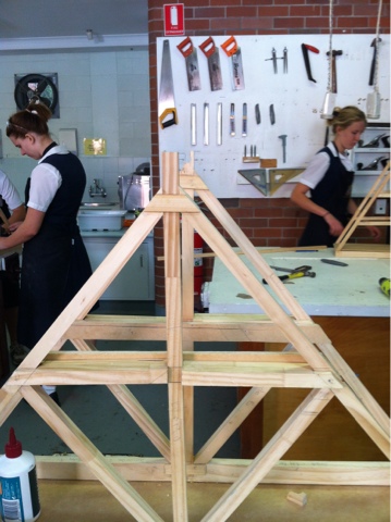
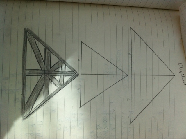
Photos of early planning

I am uploading these so I can as them to my assessment

Blog update

Last lesson ruby and I tested our trebuchet and took recordings for our handed in assessment. We went to outside boarders and the chapel because we though that that would be the flattest place and we could get an accurate shot from that. Our first two releases went in the 10m mark but the other 3 (we would release the ball 5 times to get a good average) it would a only go around 5m because it would crash into the bushes.

The results were:
Average Distance: 7564.6mm
Average Time: 2.116sec
Mass: 145.4g

We still need to record the height but I will have to ask mr ward about that and where we measure it from. We decided to to re record the last 3 distances because it is part of the assessment and it will give us something to talk about in he evaluation.

Monday, 29 October 2012

Blog Update

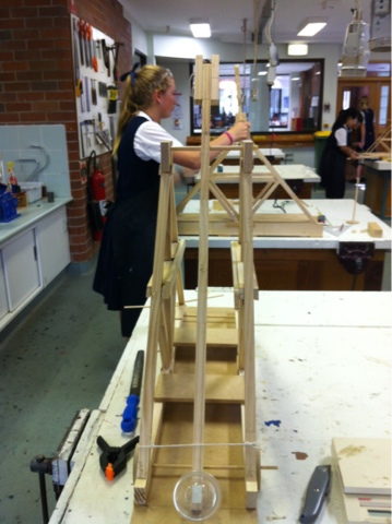
Today ruby and I got our catapult finished. It was really good. We started off by adjusting the axel at the top so that the dimensions fitted the trebuchet. We then worked on attaching the cup to the end of the propellor. We first tried making a stand for it but then Mr ward said it should be fine how it is. With the help of Mr Ward we then screwed holes in the bottom and this took a bit of adjusting so that the Asclepius in which the wheels are to rotate off can rotate. But after that, it was just a press fit of the wheels and then the catapult was ready.

First using a 1kg weight that was hooked to our swing, we propelled the ball from outside the classroom and it reached about the drains. We then advanced and added a 2kg weight and the ball went further. I think next lesson we will just reinforce the pole at the end closest to the axel because the wood is beginning to split. But after that then we will do our recordings and I will video it so I can not step by step, the process in which the catapult takes.

Sunday, 28 October 2012

Blog Update

Today ruby and I got straight into the workshop. But before we did that we made sure that we could do tomorrow lunchtime to get more of it done so that we had plenty of time to get the whole assessment done before the due date. 

We started off by finishing the extenctions and support to the top of the A-Frame, which glued well. We then got Mr. Ward to help, and Ruby drilled a hole in our sling, this was a factor that made it line up with the bottom of the A-frame, not the full catapult end. This would allow us to have more force pulling down on the weight end of the sling. 
Mr Ward then drilled a hole through the other A-frame and we managed to get the whole top part lined up with not too many issues due to the un-allignment of the frames. 

I then drilled a hole through the bottom of the sling where we would hang our weight off. I was nervous but I was able to do it fairly well and it was good that I was made to do it under controlled conditions so it was harder for me to do something wrong. I also hammered the rod through that Mr Ward measured out to be a press fit and then I sanded it smooth. 

Ruby then had the idea to cut a wheel in half and use it for the pin holder. It looks really good but we will finish it later when we know the full dimentions of our cup. 

Wednesday, 24 October 2012

Blog update

Today we glued the two a frames to the plank connecting them at the bottom. Once we did that, mr ward pointed out that our a frames were not even because of a tilt or not properly measured middle rod in the a frame. Mr ward started by drilling a hole through the top but then it snapped. Mr ward then showed how to add the reinforcements I the side so we are working on that now

Monday, 22 October 2012

Design

Today in design mr ward was away do we did theory. I managed to put the timeline onto an actually timeline and I wrote out the definition for PE and got all the rest of the assessment ready. So when I have the information, I can just write it in.

Wednesday, 17 October 2012

Blog update

Today we went ahead with making the A frame. After pushing and gluing the vertical side into the horizontal piece of wood that utter brilliantly.
we measured up the wooden frames for the long diagonal frame. Though we measured it out to what we thought should be perfect - it didn't end up that way. So when we glued one of the sides on we had to add a thinner peice of wood to it so it would e more secure.

Monday, 15 October 2012

Blog update

Today ruby and I ruled up (this time because last time it was a last minute rush because it was a mistake in progress). So we added another block of wood across the frame for the other frame. We also reinforced bits and prices with nails so that te Redfin is up to date. We measured up and cut one of the other joints to the frame and it fitted perfectly. We went to the other side but didn't have time to check it fits.
Uploaded are the pictures from lat lesson

Sunday, 14 October 2012

Blog Update

Today in design Ruby and I sanded down or connectors and glued them in. Now the connectors din't fit right so we had to nail them in at the same time. This was an unplanned process so the first nail ended up coming out the other side, rather than through the center.
However by the end of the lesson we had all the - for the A frame set into both frames and for the first, we also secured it with another piece of wood (glued) to keep it together and to keep it straight. We also made reinforcements to the tops of both A frames and the bottom of one of the A frames. I have my time line ready for my assessment, however I could not find the full assessment schedule on blackboard again so I have emailed Mr. Ward regarding that matter.

Wednesday, 10 October 2012

Blog Update

Today Ruby was here and we continued with our - of the A frame. By the end of the lesson we had the two sides for each glued together so they can be attacted properly to the fame. This lesson I also traced out reinfrocements for the top of the frame. What I have planned to do before we finish the A frame is to


  1. enforce < > in with screws
  2. Renforce base with pva glued wood
  3. drill hole for the axel to pass through
etc...

i also broke the drill saw today and learnt to saw a few millimeters away from the cut line and then sand the rest (this has been really helpful)


I have started my timeline

Lined Timeline of Trebuchet

·    3-5bc: The Chinese were thought to have invented the first trebuchet (Huihui Pao) which, in design, was very similar to a sling, with 15-45 men used as the counterweight.
·    300ad: Greek and Roman (Soldiers of Piliip of Macedonia created their ballistas (a different form of trebuchet) which design was similar to a crossbow and is thought to be the primiary inspiration for the catapult/trebuchet. Difference is that ballistas used two wooden arms rather than one
·    350ad: Romans created mangoles which was similar to the ballistas however they only had one wodden arm enabling them to hurl stronger and sharper objects at a greater speed.
·    965 c:  First recorded hand-trebuchet in Greece.
·    6th c:    “balliustae revolving in both directions” this appeared in Byzatium
·    12th c: French created the trebuchet which turned to be the true siege engine of mass destruction and at the time it’s power and force was unmatched. It used only one wooden arm which rested on a pivot point. Because the point was used as a leaver, the object could be hurdled at a much greater spped and strength.
·    Middle Ages: catapults were the major siege weapons because of there extreme effectiveness in battles. As history went on, the catapult evolved, capable of more damage. The catapults were used to fire projectiles (as much as three hundred pounds) as well as bodies of people and animals who have died of a disease, into the castle walls.
·    1097:   Emperor Alexios I Kommenos in the Siege of Nicaea was reported to have invented a new form of trebuchet.
·    1211ad: The siege of Castelnaudry was the first time that a trebuchet is mentioned.
·    1124:   The Crusaders used great siege engines for the Second Siege of Tyre in Lebanon. It is believed that these great siege engines were counterweight driven trebuchets.
·    1187:   The first pictorial evidence of counterweight driven trebuchets appeared in a military manual written for the military leader Saladin.
·    1191:    for the siege of Acre two large trebuchets were used by Philip II
·    1268   First recorded Chinese counterweight trebuchets in the Mongol siege to Francheg and Ziangyang.
·    1304:   A giant trebuchet named “warwold” was created for the English army
·    1475:   The introduction of gunpowder caused less need for trebuchets over cannons however the trebuchet was still used in the siege of Burgos
·    1779:   When British forces were defending Gibraltar the constructed a trebuchet because their cannons were unable to fire long enough.


Tuesday, 9 October 2012

Blog Update

Today Ruby was away so I worked by myself in the workshop today. I started straight away and continued working on the materials from last term. Today I ruled up more connections to go across the middle of the A-Frame. To ensure stability within the frame we are having two sides to this connection. So this lesson I ruled up the markings and used the drill saw and started cutting them to shape.

Sunday, 16 September 2012

Blog update

Today we went ahead with making the A frame. After pushing and gluing the vertical side into the horizontal piece of wood that utter brilliantly.
we measured up the wooden frames for the long diagonal frame. Though we measured it out to what we thought should be perfect - it didn't end up that way. So when we glued one of the sides on we had to add a thinner peice of wood to it so it would e more secure.

Wednesday, 12 September 2012

Blog Update

I'm going to try my blog in a different layout, see if it works:

Lessons Learned

  • That for major holds in the A frame, to nail the fittings in with the PVA glue so that the holds will hold the parts together
  • Accross the base and other major joins in the A-frame, have another peice of timber glued accross in order to fully secure the frame. 
  • Have thicker blocks to hold the two A-frames together at the same distance appart. 
  • Use pre-made wheels (equipment available)
  • Watch the length of the leaver so that the A-Frame is long enough to compact with the length of it. -Mr Ward is having to change his
  • Mr Ward is good at cutting big pieces of wood to a good measurement
What we did this lesson
Today we started building the T shape for the A frame. We are going to use the box fit and we cut of the box needed for this. We have it ready to fit even through it could have been more accurate. Next lesson we will be able to glue it.


I am still not overly confident with the machines but i guess that will come with experience.

Tuesday, 11 September 2012

Blog Update

Yesterday Mr Ward showed us how to make a house fit in which it is one point in which is suppressed and then with the added glue, it will make a very tight and secure fit.
Ruby and I went on to creating the dimentions to our frame. We are planning to go into the workshop in the next possible lesson

Monday, 10 September 2012

Tips From http://www.butlercc.edu/engineering/en115/en115_basic_treb_design.cfm

Object
Design guidelines
Material
Counterweight75 to 100 times heavier than projectileshould be adjustable
Armangle should be about 45 degrees when cocked; upper part of arm should be 3 to 5 times longer than the lower endpvc pipe
Base and frameworkmust be heavy enough to support arm and counterweight and for precision, yet light enough to have a high material efficiencypvc pipe
Sling or ropeshould be slightly shorter than upper part of the throwing arm (for starters, that is); too short will release the projectile too early, higher trajectory; too long will drag the ground, lower trajectoryany material
Sling release pina more hooked prong will hold the sling loop longer than a straighter one. ie a prong less hooked or in line with beam gives an earlier release, higher trajectory;a prong more hooked or forward-pointing gives a later release, flatter trajectorymetal or other material
Projectilea heavier projectile tends to pull the loop off the prong earlier than a lighter projectile does. heavy projectile gives earlier release, higher trajectory; light projectile gives later release, flatter trajectorytennis ball-provided
Triggeryou need some way to release the projectile in a repeatable wayany material
Troughthe projectile needs to slide down some type of guide; friction will be important hereany material
*Base wheels-optionalwheels added to the base may increase distance; repeatability(? )any material

Blog Update

Today we went over the new assessment. Mr Ward went over his planning for his trechubet and and how it is to work. There seem to be alot of ways in which to approach this unit, some trechubets are sturdied not on wheels but on an axel. However I think having wheels will make the trechubet more stable than if it were held by just a few wheels.

Ruby and I got to work on our planning and with images of trechubets open, I worked out a design for the framing of our catapult. I rember learning somewhere that triangles are the sturdiest shape to build a from so I took that Idea and made the framing of the trechubet many trianges. We worked on the height to length ratio also.

Thursday, 6 September 2012

Blog Update

This week was a good fun one. In our first lesson we had our last adjustments to our kart and i just adjusted the glue to make sure the wire at the front stuck. We also discussed what to do for our next assesment. Zara wanted to build some sort of wood work and we all wanted to make rockets, though I had allready done that in year 5 so I wasn't as keen. But then I had the idea to make a catapult (partly because I was thinking of Lord of the Rings and other because my brother had just found a nerf gun). But anyway, the idea was accepted and everyone seemed keen.

The race day, well I got kicked out on the first round -very close through - and I lost to Amber who won so, well, luck of the draw. I was on timer and it kept me busy so I was happy.

Last lesson we discussed more on our new unit which is building a trechuet (catapult). It looks really exciting and I am actually really keen to do the history about it because medieval history is pretty much my favourite era to look at.

I will be working with ruby and we started researching designs for our machine and we have found some variables in the design


  • wheels or no wheels (we already know from a video that Mr Ward showed us that it works better with wheels because it increases the thrust of the object fired
  • The holder can be either a spoon shape, a "sling-shot" type shape, of a netted basket
  • How much scaffolding is on the model
  • what is used as the weigh (usually it is a box that the weight could be changed)
  • length of the rope